Transition to ADS-B
During World War II, a scheme was enacted to identify friend or foe (IFF) using radio-frequency interrogation/response codes. The response codes originally consisted of two octal digits (6 bits total), allowing 64 possible codes.
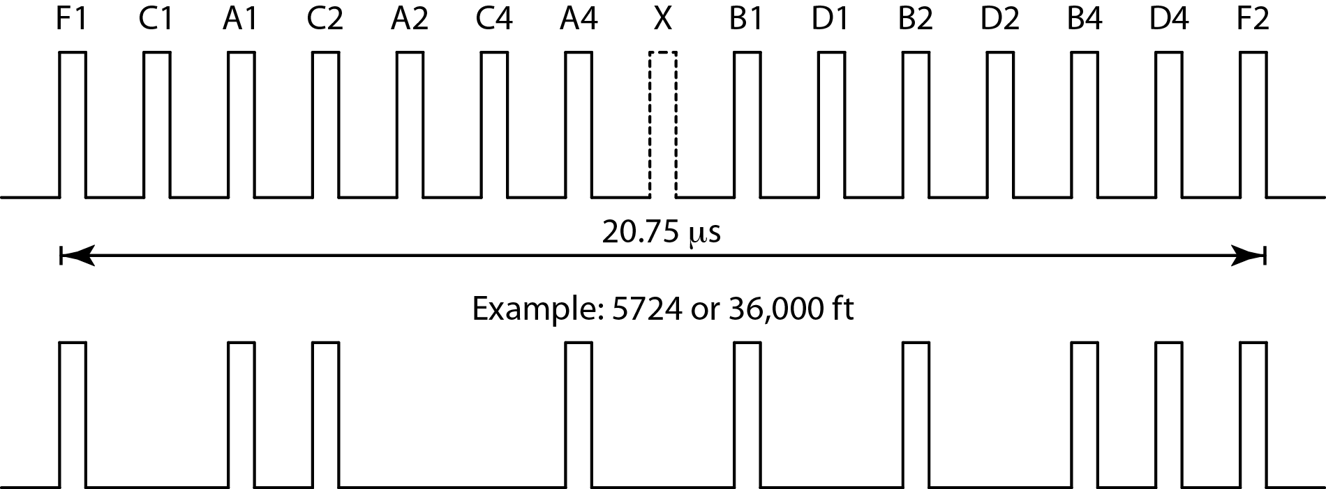
During the 1950s, the pulses became shorter so that more of them could fit within the 21 μs package, resulting in 12 bits of information represented as four octal digits for 4096 codes (sandwiched between two framing pulses at the ends). This scheme became commonplace in international aviation, and is still used today—known as Mode A (temporary identity) and Mode C (altitude). These modes rely on pulse amplitude modulation: blasts of RF power at 1090 MHz may be present at the appropriate time to set the corresponding data bit. The overall format is shown below. Pulses are 0.45 μs in duration on a 1.45 μs cadence (1.0 μs gaps). The first and final framing pulses are always present. Sadly, the X-bit is never used (would be super-useful to have this indicate whether a transmission is Mode A or Mode C). The interrogator knows which of the two it asked for (based on differing interrogation signal pattern), but as passive listeners, it can be ambiguous.
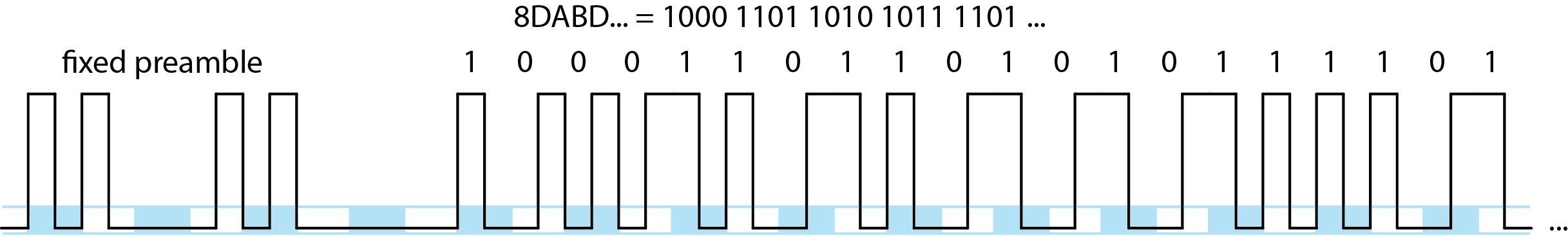
In the mid 2000s, Mode S transponders entered the scene, using 56 bits of coded information (including parity check) to communicate more versatile data, including permanent aircraft identification, altitude, assigned Mode A identity (squawk) code, as possible examples. Still at 1090 MHz, the transmission scheme switched to pulse position modulation: guaranteed transitions between zero power and full power in every one-microsecond symbol frame, but the direction of the transition within the frame conveys binary one or zero. Like Mode A and Mode C, Mode S is also sent in response to interrogations; the format of the transmission (what information is sent) depending on the type requested by the interrogator. The figure below shows the beginning of an example Mode S pulse sequence. The blue scale bar defines 1 μs frames; note the data values correspond to direction of the mid-frame transition (or alternatively, the value in the first half of each frame).
More recently, Mode S type transmissions have been augmented to 112-bit formats that are spontaneously transmitted by the airplanes (e.g., once per second) independent of interrogation. This is still at 1090 MHz and called "extended squitter," or alternatively ADS-B (for punishment, look up what this stands for; you may be sorry). Information communicated may be similar to Mode S, but also may include latitude and longitude, or velocity, heading, and vertical rate, or a number of other data-rich transmissions.
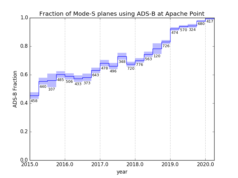
So far so good: TBAD is able to interpret all these forms of communication at 1090 MHz. ADS-B was added as a capability in late 2014, and the plot below shows the adoption rate (FAA target is full compliance by 2020).
The binning is quarterly. The numbers represent the total number of airplanes detected with some form of Mode S or ADS-B transmissions in that period. Shaded bars indicate the one-standard-deviation range given binomial sampling statistics. Overlapping shaded bars indicate statistically compatible levels. As of March 2020, it appears that virtually all Mode-S aircraft over Apache Point were indeed broadcasting ADS-B packets.
So far the story is a happy one for TBAD. But it's about to take a turn. Part of the ADS-B effort involves offloading some of the radio traffic to another frequency, so that the 1090 MHz scene is not so crowded. General aviation airplanes (those remaining below 18,000 ft) are encouraged to operate at 978 MHz in what is called UAT (universal access transceiver). Transmissions are either 276 or 420 symbols long, consisting of a 36-bit sync word, 144 or 272 bits of information (payload), and 96 or 112 bits of Reed-Solomon error-correction code.
All TBAD units built before 2019 were completely deaf to 978 MHz. Moreover, the modulation scheme is no longer simple RF pulses easily detected and decoded: it's a binary frequency shift keying (FSK) scheme wherein the modulation is ±312.5 kHz and symbol duration is a short 0.96 μs (leaving less than 2 radians of phase development per symbol: hard). Power levels are somewhat lower than the 1090 MHz scheme.
As of early 2019, we have a hardware prototype capable of successful dual-band operation at 1090 MHz and 978 MHz. Doing this requires several modifications/augmentations to the original TBAD system, including:
The sections below elaborate on these pieces. If contemplating an upgrade to dual-band capability, see this page.
At the front-end, precision-designed patch antennas make use of transmission line tricks to simultaneously make 978 and 1090 MHz efficient.
Compare the response below of the dual-band patch to that of the single-frequency design on the Pictorial Tour page.
What's plotted is how much RF amplitude is reflected back when used as a transmitter, so that a low value corresponds to little reflection and thus good transmission efficiency—or coupling to free-space. For context, reflected power goes like the square of reflected amplitude, so everything below the 0.1 level on the plot is less than 1% reflection; below 0.2 is <4%, etc.
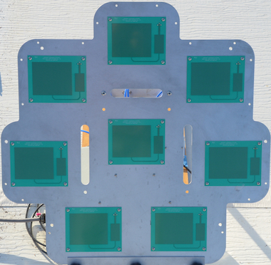
And here is a picture of the assembled 8-patch dual band antenna array. The plate external dimensions and hole patterns are identical to older single-band 8-patch arrays.
The front-end RF handling of the dual-band discriminator is very similar to the 1090-only design, except a diplexer replaces the narrow-band filter and each frequency gets its own power detector. Then each frequency is processed separately in terms of threshold-based decision making as to in-beam transmissions, signal saturation, etc.
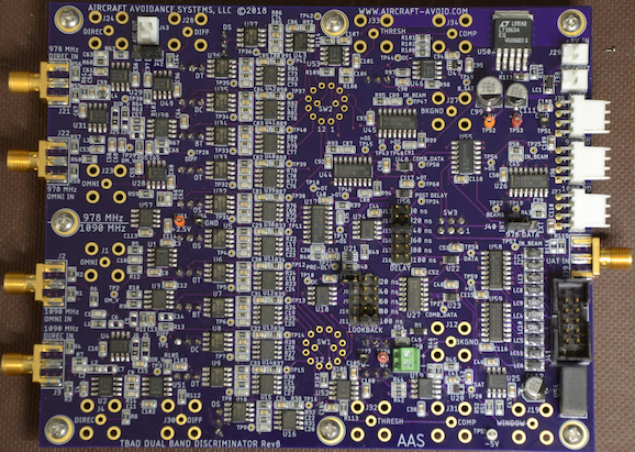
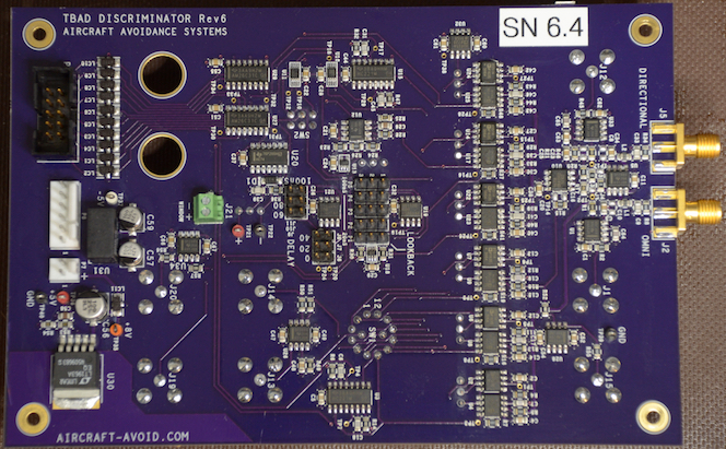
One challenge was shoving this roughly-doubled functionality into a footprint similar to the original single-band discriminator board so that an upgrade path could fit within existing space constraints. Below is a picture of the new discriminator board (left) compared to the original (right).
What has been described so far is sufficient to properly detect transmissions from aircraft emitting either 978 or 1090 MHz and react accordingly to ensure safe operation of a laser through airspace. TBAD also historically produces a serial data stream that can be monitored and recorded by a logging computer for system characterization and post-analysis. Especially useful are transmissions that convey aircraft 3-D position (like ADS-B at 1090 MHz) for verification of TBAD performance as a function of offset angle from boresight (as demonstrated at the bottom of the tour page).
Because each UAT transmission also contains positional information, it would be a shame to ignore—even though the system would operate safely absent informational logging. This turns out to be much more complicated at 978 MHz than at 1090 MHz, for reasons described above. A scheme involving a digital mixer, fast analog-to-digital converter, and field-programmable gate-array (FPGA) demodulation produces a data stream that suits TBAD's microcontroller-based signal detection and recording scheme. An example of the leading edge of a lab-bench-generated 978 MHz FSK-modulated signal appears below.
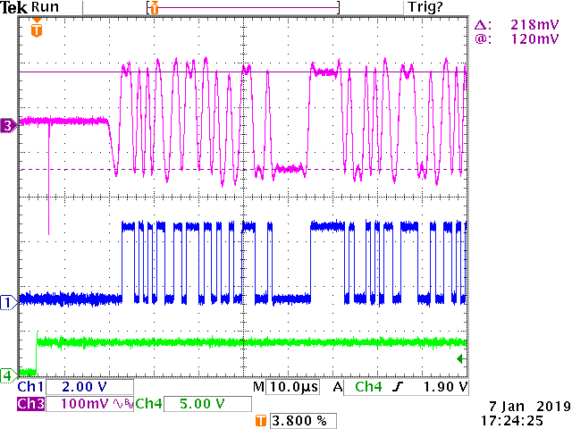
The blue curve is the recovered digital signal, while the magenta curve is the FPGA's representation of the frequency evolution. Symbols are 0.96 μs in duration.
The 978 MHz UAT data is merged with the 1090 MHz data (collisions possible but infrequent), and sent to the decoder, whose microcontroller is on the lookout for new signals. Expected differences in the beginning of the data sequences (distinct patterns in the sync word for UAT vs. preamble for Mode-S and ADS-B vs. the pulse pattern of Mode-A/C) allow the microcontroller to know how to record the rest of the data stream, and for how long and at what cadence.
In the case of UAT data, all but the first 12 bits of the 276-bit or 420-bit sequences are transmitted across the serial line for consideration (the first 12 are "consumed" in the preamble determination, followed by a delay to align to byte boundaries).
What TBAD transmits and the logging computer receives might look like the following hexadecimal code:
DDA4E200A9503A2EB0655956D207197B062700F800B9B3F88B2F47FA0FD10495A9where the first 6 characters (nibbles; 4-bits each) represent the last 24 bits of the 36-bit sync word (EACDDA4E2, in its entirety). The last 96 bits (24 hexadecimal characters), starting at B9B3... contain the Reed-Solomon error correction data.
The logging software receives this text string (the example above is the 276-bit transmission; the other is longer at 420 bits—not shown) and figures out if the Reed-Solomon algorithm spots any damaged bytes (within either or both the data payload and error correction blocks). The shorter 276-bit transmission is capable of correcting up to 6 bytes, independent of how many bits are damaged in each (the longer code can correct 7).
If few enough errors exist, the logging code strips off the sync word and error correction, presenting only the corrected pattern to the file:
00a9503a2eb0655956d2071900062700f800Note that one byte was corrected in this case: 07197B062 in the original was corrected to 071900062. Even though this represents 6 bits corrected, it only consumes one of the six available bytes that may be corrected.
Finally, the logging code can insert practical information into the file about the transmission. In this case, the plane carrying ICAO (permanent) registration number A9503A was at latitude 32.8282, longitude -117.1834, and altitude 1800 ft.
In early 2019, the TBAD system became capable of detecting UAT-transmitting aircraft all the way through error-corrected logging. An example of a 978 MHz capture looks as follows in the log file:
2019-01-15 20:46:13.459 o08a9503a2ea7935960ba081900aa2e00af066a0025ed2d0b5aa4c0a0000820000000...JFx0AB err 0/0Notice that a mix of short and long codes exist in this clip. The err 0/0 indicators signal that no errors were found in the sync word or in the Reed-Solomon correction scheme. So in these cases, the information was perfect and did not need correction (of the 29 events in this first ever TBAD UAT capture, only one needed correction and none were beyond repair). The three red O appearances indicate that the omni-channel saturated (close passage), which in turn changed the shutter status from open (o at the beginning of the code) to shut (s).
UAT: A9503A air 32.8040 -117.1562 2200 101/295 576 light 1200**** 22
2019-01-15 20:46:14.297 o00a9503a2ea7a1596094081900ae2e00ed00...JFx044 err 0/0
UAT: A9503A air 32.8041 -117.1566 2200 102/295 832
2019-01-15 20:46:15.520 o10a9503a2ea7b759605c085900b22d80e80000000000000000000000000830000000...JFx006 err 0/0
UAT: A9503A air 32.8044 -117.1572 2300 101/296 832
2019-01-15 20:46:19.240 o00a9503a2ea801595fac085900be2d80d800...JFx0DA err 0/0
UAT: A9503A air 32.8052 -117.1591 2300 102/297 768
2019-01-15 20:46:20.295 o00a9503a2ea815595f7e085900be2d80df00...JFx021 err 0/0
UAT: A9503A air 32.8054 -117.1596 2300 102/297 768
2019-01-15 20:46:26.487 s10a9503a2ea897595e64089900d22c81080000000000000000000000000890000000O..JFx0E6 err 0/0
UAT: A9503A air 32.8068 -117.1626 2400 103/300 960
2019-01-15 20:46:27.257 s00a9503a2ea8a9595e40089900d22c010f00...JFx0E7 err 0/0
UAT: A9503A air 32.8070 -117.1630 2400 102/301 960
2019-01-15 20:46:29.299 s08a9503a2ea8d7595de808d900d62b812e066a0025ed2d0b62a4c0a00008b0000000O..JFx000 err 0/0
UAT: A9503A air 32.8075 -117.1640 2500 102/301 1088 light 1200**** 24
2019-01-15 20:46:30.578 s00a9503a2ea8f1595db408d900da2b00ed00...JFx01E err 0/0
UAT: A9503A air 32.8078 -117.1645 2500 102/302 832
2019-01-15 20:46:31.732 s10a9503a2ea90d595d8008d900da2b00d800000000000000000000000008c0000000O..JFx011 err 0/0
UAT: A9503A air 32.8081 -117.1651 2500 102/302 768
2019-01-15 20:46:40.327 s08a9503a2ea9df595c0c091900ee2a80c809df5614e6c40b1ea4c2a0000900000000...JFx0DF err 0/0
UAT: A9503A air 32.8103 -117.1691 2600 103/305 704 light N7DU 7
2019-01-15 20:46:42.944 s10a9503a2eaa1d595b9a091900e62b80c80000000000000000000000000910000000...JFx02B err 0/0
UAT: A9503A air 32.8110 -117.1703 2600 104/303 704
Each transmission is accompanied by a brief dissection of the content: airplane ID; airborne (vs. TIS-B ground translation vs. ground uplink, etc.); 3-D position (lat., lon., and altitude in feet); speed (knots)/heading; and vertical rate in feet per minute. Some transmissions include additional information such as aircraft class, tail number or (often) squawk code, and which message opportunity was used (relevant to signal timing). In this case, we have a light aircraft flying WNW at just over 100 knots, climbing out (of Montgomery Field) under VFR (1200 squawk code).
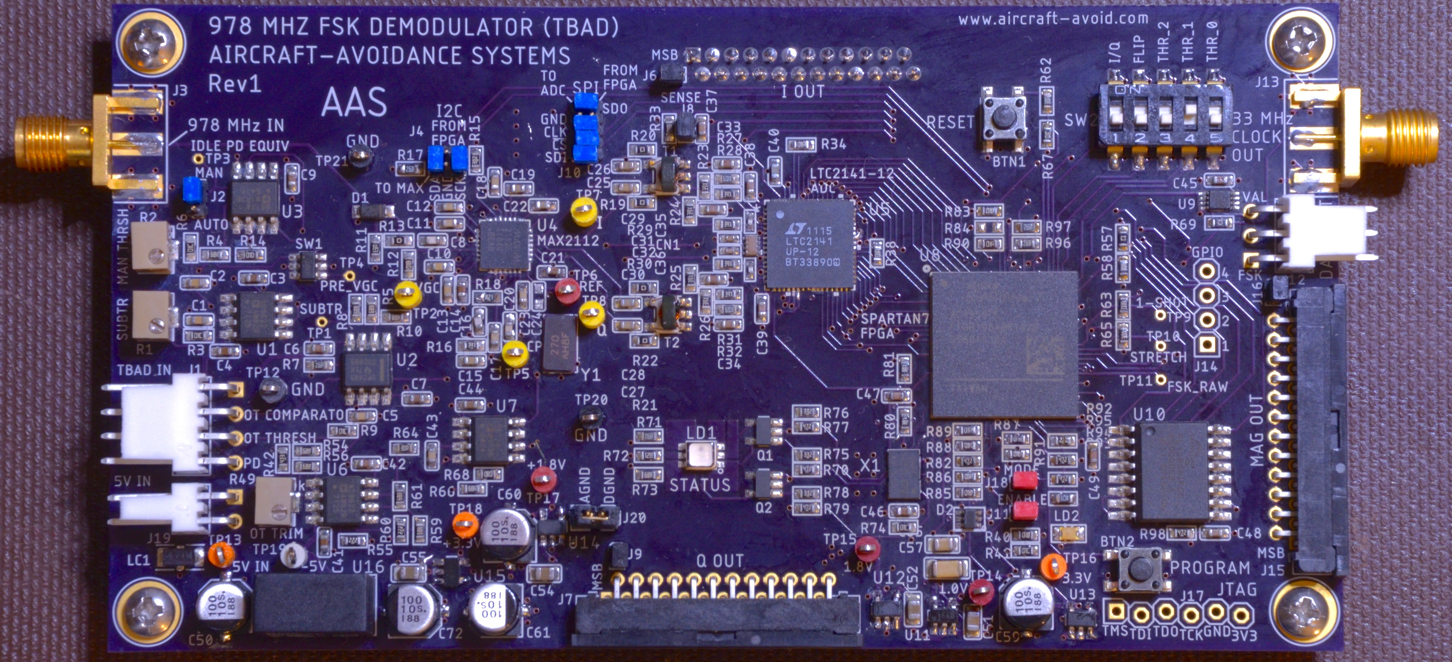
As of February 2019, the FSK demodulation components have been packaged onto a single circuit board augmenting the discriminator unit to supply data to the TBAD logging operation. The image below (click for full resolution) shows the prototype PCB. Measuring 127×67 mm, the board fits into the same weatherproof box as the discriminator.
If you already have a TBAD unit operating at 1090 MHz, should you upgrade to the dual-band design? This page offers some thoughts on the matter.